What is a photographic emulsion?

Figure 1 - Women separating egg whites and egg yolks as the first step in the manufacture of silver albumen photographic paper from Josef Maria Eder's Ausführliches Handbuch der Photographie, Book IV, part 1, 1898 edition.  In the public domain in the US.  See hyperlink in text for more information on the process.

Figure 1 – Women separating egg whites and egg yolks as the first step in the manufacture of silver albumen photographic paper from Josef Maria Eder’s Ausführliches Handbuch der Photographie, Book IV, part 1, 1898 edition. In the public domain in the US. See hyperlink in text for more information on the process.

A photographic emulsion is a fine suspension of insoluble light-sensitive crystals, for example silver bromide, suspended in a colloidal solution.  Basically, this means that while the crystals are not themselves soluble in water, they can be suspended in a material, such as gelatin, which is then allowed to harden thereby suspending the crystals permanently.

The emulsion is layered onto a substrate such as glass or a film, e.g. nitrocellulose or plastic.  In the nineteenth century the emulsion material was most often egg albumen, and this created an entire industry of manufacture that started with the separation of thousands of egg yolks and whites as shown in Figure 1.  Modern photographic emulsions are made from gelatin, which is partially hydrolyzed (boiled) extract of animal cartilage and bone – hence the classification of silver-gelatin print.

The light sensitive emulsion is generally manufactured, as suggested in my previous blog by dissolving silver nitrate and potassium bromide in a hot gelatin solution and allowing the crystals of silver bromide to precipitate out in the gelatin.

So now, we have the fundamental elements of a photosensitive material.  You can do this yourself at home, if you are industrious, and there are even commercial kits to help you.  If you want to do albumen printing you can purchase kits from Bostick and Sullivan. As should be obvious from our discussion of color photography and color movies, the fundamental silver halide process is ubiquitous.

Curiously, how it works, what the fundamental mechanism of light sensitivity is, was largely a mystery for the first century of photography.  That mystery is the subject of my next technical blog.

What is a silver halide?

Figure 1 - The Periodic Table of the Elements from the Wikicommons and in the public domain.

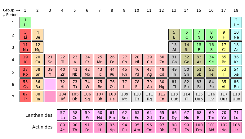
Figure 1 – The Periodic Table of the Elements.  The halide group is shown in yellow. From the Wikicommons and in the public domain.

In considering silver halide chemistry, the first question is exactly what is a silver halide.  A silver halide is a compound formed from silver and a halogen.  That didn’t get us very far.  What’s a halogen?  If we look at the period table of the elements (be sure to click on Tom Lehrer’s version) in Figure 1, the yellow group 17  are the halogen elements: Fluorine, Chlorine, Bromine, Iodine, and Antimony.

Figure 2 - The crystal structure of silver bromide.  The silver atoms are the red spheres the bromide atomes are the pale blue spheres.  Form the Wikicommons and in the public domain.

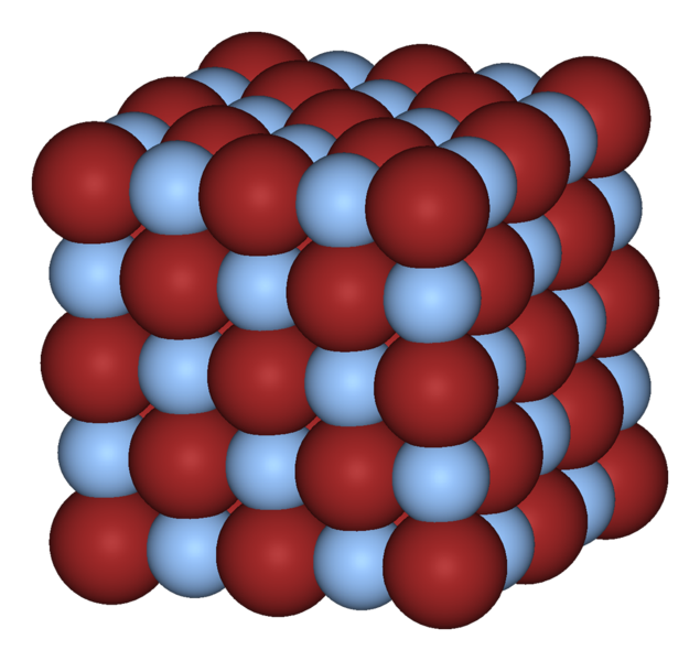
Figure 2 – The crystal structure of silver bromide. The silver atoms are the red spheres the bromide atoms are the pale blue spheres. Form the Wikicommons and in the public domain.

A silver halide then is a crystal formed between silver and one of these Group 17 elements.  Without getting into too much detail the silver metal gives away some of its electrons to become positively charged.  These are scarfed up by the halogen to become negatively charged.  The halogens ions all have a charge of -1 (electron’s worth of charge).  That’s why they are grouped together. Since opposites attract the silver and halogen ions attract one another and form very compact and structurally well-defined crystal structures.  These crystals typically take on a cubic form as shown in Figure 2, for the important photographic material silver bromide, where the red spheres are the silver atoms and the pale blue ones are the bromine atoms.  The other common photographic silver halides are silver chloride and silver iodide.

Silver bromide is not soluble in water.  This is convenient.  If you mix a solution of silver nitrate in water with potassium bromide in water, the silver and bromine switch partners to form silver bromide and potassium nitrate.  The potassium nitrate stays in solution.  The silver bromide precipitates into fine silver bromide crystals, ready to be washed and put into a photographic emulsion.  What an emulsion is will be the subject of my next technical blog.


The Physics of Light Detection – Part 2

Figure 1 - Valence and conduction energy bands in a crystal

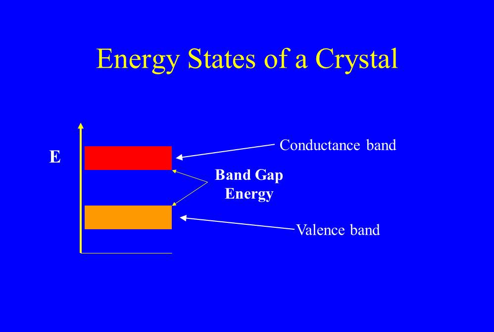
Figure 1 – Valence and conduction energy bands in a crystal (c) 2013 DE Wolf

How do we classify matter?  One of the ways, one that most of us are familiar with, is in terms of “the state of matter.”  Is it a solid, a liquid, or a gas?  If you take some ice cubes, a solid, and stick them inside a bottle they maintain their ice cube form.  They are unperturbed by the fact that they are in the bottle.  If you melt the ice cubes, they become water, a liquid, and take on the shape of the bottle, but remain confined by gravity to the bottom of the bottle.  If you vaporize the water into steam, a gas, the steam fills the entire bottle and conforms to its shape completely.  Actually there is a fourth state of matter to consider.  If you ionize the water by ripping off its valence electrons and maybe even some of the lower energy ones, it become a charged gas, referred to as a plasma.

At an atomic level, the atoms in a gas are largely oblivious of one another.  This is because they seldom come in contact with one another.  Their interactions, with say light, are single atom events and independent of what the other atoms are doing.  In a liquid the atoms start to interact with one another.  In a solid the interaction is complete.  The atoms form well defined structures called crystals.  The crystal now interacts with light as a unit.  As a result, we talk about the energy levels of the crystal, no longer of the individual atoms.

Because of this cooperative effect, the energy states start to blur out and become a continuum.  However, there is still an energy gap between the states of bound valence electrons, called the valence band [of energy levels], and the energies of liberated or free electrons, called the [conductance band].  I’ve illustrated this schematically in Figure 1.

(BTW Figure 1 gives you the opportunity to thumb your nose at your high school or physics college teacher, who always insisted that you label axes of a graph and marked you down if you didn’t.  The y axis is energy, but there is no x axis label.  This diagram is called a Jablonski diagram in physics.)

How does an electron gain the energy to escape from the valence band to the conductance band in a crystal.  It can be done with heat, or electrical energy, or with light.  A photon of light can be absorbed and give the electron enough energy to escape.

You can define three types of solid materials on the basis of how easy it is to liberate the valence electrons.  In conductors, typically metals, the band gap energy is so small that it occurs very easily at room temperature.  Many electrons go into the conductance band, and if you attach the conductor across the terminals of a battery a current readily develops.  In insulators, the band gap is huge and precious few electrons are in the conduction band.  The material does not conduct electrons.  Finally, there are in between materials, called semiconductors, which need a boast to get the valence electrons into conduction band.

One such boast, as we’ve already described, is light.  This kind of semiconductor/ light interaction is the basis of both analogue and digital photography.  As we will see, it explains how silver halide films work, how camera light meters work, and how digital camera sensors work.

In the next few technical blogs, I’d like to explore the inner workings of the silver halide film process.  Breaking it all down, we need to sequentially consider:

  • What is a silver halide?
  • What is a photographic emulsion?
  • How is the latent image formed?
  • How is the latent image developed?
  • How is the developed image fixed or prevented from further interaction with light?

The Physics of Light Detection – Part 1

Today, I’d like to begin a discussion of the physics behind light detection. By light detection I mean both how analogue films work and how digital camera sensors work. Surprisingly, the answers are closely related because both work as a result of semiconductor physics.

In discussing these topics, we are fundamentally talking about how light interacts with matter and we already know the answer. Light interacts with matter in complex, varied, and often beautiful ways. Consider a rainbow, which is the interaction of light with spherical water drops inside clouds. That is a process called refraction and spectral dispersion. Consider the mobius strip photographs in my “Manmade gallery.” Those spectacular colors are created by a process called optical birefringence.
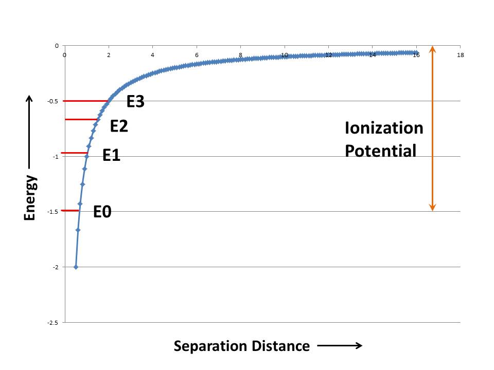
Figure 1 - The potential well or Curve of Binding Energy (c) DEWolf 2013

Figure 1 – The potential well or Curve of Binding Energy (c) DEWolf 2013

But let’s keep things reasonably simple here. We need to understand our subject qualitatively, not quantitatively, which means, yay, no equations!

OK, so we know that atoms are made up of protons, which are positive charges, and electrons, which are negative charges. Opposites attract. So given half a chance an electron will rush towards a proton. That’s how lightening works! Ka-boom!

Now let’s hold an electron some distance away from the proton. You will feel the force of attraction in your fingers. This is referred to as potential energy, because if you let go the electron will move very quickly towards the proton, that is there is the potential for motion, aka kinetic or motion energy. By convention, because of the attractive nature of the force, the energy is said to be negative. We can plot the energy as a function of the distance between the electron and proton. In general the electron will seek the lowest energy. That is, it will try to go to the bottom of the well. The bottom of the well here is at minus infinity, which is a very cozy place for our electron to hide out.

The well of Figure 1 is what the electron sees. An electron can only be at the bottom of the well if it has no kinetic energy. If it has kinetic energy it will be a bit higher in the well. Next, it turns out that the electron cannot have any energy value that it wants. Only very discrete and well defined levels exist. This statement about discrete states is the foundation of the science of quantum mechanics. While it may seem bizarre, it is never-the-less borne out by countless supporting experiments. It is on a very sound theoretical and experimental proof-of-the-pudding foundation.
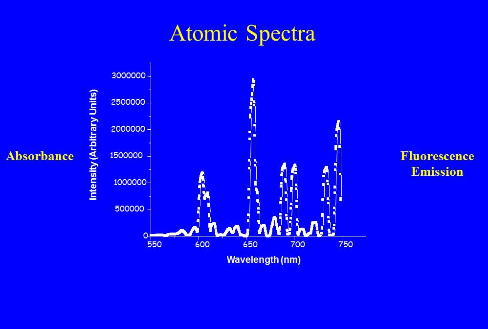
Figure 2 - Atomic spectrum of the plasma glow of a HeNe laser (c) 2013 DEWolf

Figure 2 – Atomic spectrum of the plasma glow of a HeNe laser (c) 2013 DEWolf

In Figure 1 I’ve shown some energy levels where the electron can reside. The electron can move between these states, but only if you give it more energy, because energy has to be conserved in physics. Where does that energy come from? One possibility is light. If the photon of light has exactly the right amount energy, is exactly the right color, it can be absorbed and elevate the electron to the next allowed energy level. You can also accomplish this by heating the system up, or bombarding it with a spray of electrons. Always a precise amount of energy is absorbed, called one quanta. Often the electron falls back to the previous state. To do so it has to emit light of the precise color again. Consider Figure 2, which shows the “plasma glow” of a Helium Neon laser. The plasma glow emission is caused by transitions between lots of states and is created by showering the gas with a beam of electrons. The emitted light is a set of very sharp discrete wavelengths.

The one last critical point is that if you give the electron more than a certain amount of energy, referred to as the ionization potential, it can escape the proton all together. It becomes a free electron!  I’ve shown the ionization potential (change in energy required to take the electron from it’s lowest energy level to the top of the binding curve) in orange.

In atoms that have more than one electron, the electrons sequentially fill up the energy levels.  Two electron cannot exist in the same state.  The term state is not quite the same as the term energy level.  But that doesn’t really matter for our discussion.  What is important is that the electron with the highest energy, the one that is nearest the top is the most active electron.  It is referred to as “the valence” electron and is most likely to become ionized and escape from the atom or, in fact, to interact with neighboring atoms.

The Bottom Line

The important points for our discussion of light detection in photography are:

  • electrons in atoms occupy specific energy levels
  • the most active electrons are those with the highest energy, referred to as valence electrons
  • light can cause electrons to move between energy levels
  • given sufficient energy an electron can be ionized and escape from the atom
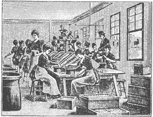
Subtractive color films

Today I want to talk about subtractive color films.  Take a deep breath.  For those who want the details I am going to get a bit technical.  Two good sites, consulted here, where you can find additional information are the Wikipedia site on Kodachrome and an excellent site from the Physics Department at the University of Colorado.

I think that after our discussion of Technicolor you can see the appeal of a film where everything is built in – no registration, no bonding, no fuss.  So basically we are talking about a film with three emulsion layers each dyed with one of the primary colors.

HSV-color-Circle

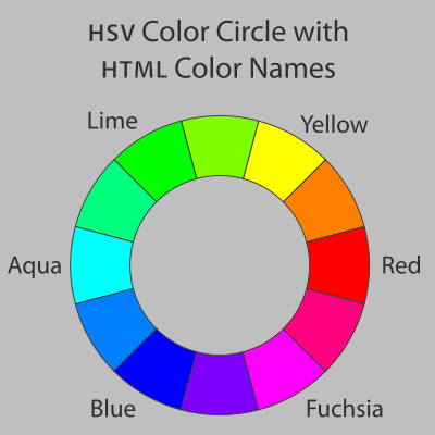
Figure 1 – The RYB or HSV color circle showing color complements. From the Wikicommons by Jacoblus under creative commons license.

Let’s begin with something that I haven’t yet shown you, namely a color wheel.  So-called color spaces are very complicated.  In addition to the mix of the colors you need to worry about hue, saturation, and lightness.  If you work with Adobe Photoshop, you will be familiar with this.  But let’s leave these issues for another day and consider Figure 1, which shows the simple color wheel that describes the Red, Yellow, Blue color system.  The point here is that the complement of yellow is blue, of red is aqua (aka cyan), and of (lime) green is magenta, etc.  Each of these colors will remove its complement, when light is passed through or reflected off it.  So to get yellow remove blue and vice versa.OK so again, in a subtractive film like Kodachrome we have three layers of emulsion one for each of the primary colors.  Each emulsion layer consists of a silver halide with a chemical called a “coupler.”  The coupler will undergo a reaction during the development and form a dye wherever there is free silver. Coupler can be added either during manufacture (eg. Ektachrome, where little oil droplets in the emulsion contained the coupler) or during development (eg. Kodachrome).  The first is called a substantive film and the latter is called a non-substantive film – because the coupler is or is not a substantive part of the emulsion.  Non-substantive films tend to be sharper, or finer grained, because the emulsion is thinner

Needless-to-say development was complicated, and as I’ve said before required very precise temperature control.  For Kodachrome this was out of the reach of amateurs.  Ektachrome could be developed at home by the brave of heart.

Obviously, there’s a lot more to it and the Devil is in the details.  For instance, silver halides are intrinsically blue sensitive.  By chemical modification red or yellow sensitivity could be added.  However, these red and yellow sensitive layers were still blue sensitive.  So to complicate matters the blue layer was placed on top of the stack and it was separated from the other layers with a blue absorbing that is a yellow filter layer.  However, the basic concept and fundamental point to remember is that of three separate emulsions each with a coupler that enabled them to be dyed for a particular set of complementary colors.

Kodachrome was introduced in 1935.  It served as a very fine and special color movie and still film.  There is a film clip circulating on the web and claiming to be a 1922 Kodachrome film test.  It is worth watching for its wonderful soft and beautiful color.  It was taken by Eastman Kodak as it tried to develop viable color processe.  However, the film was taken by an early Kodachrome process similar to the two color Technicolor process and not the commercial Kodachrome process ultimately released.

Additive and Subtractive Color

Color Receptors Human Eye

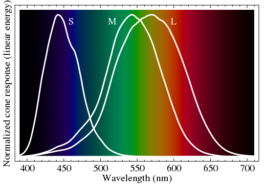
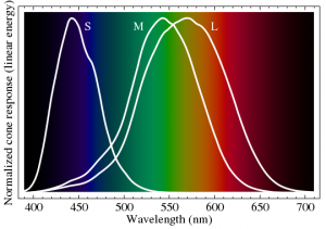
Figure 1 – The spectral response of the S, M, and L photoreceptors in the human eye, from Wikimedia and in the public domain

I’d like to discuss further the nature and development of color photography.  Always key to understanding color is the nature of the human eye.  Figure 1 is one that we have have seen before.  It shows the response of the human eye to color.  The human eye has three types of color receptors, S, M, and L cone types, each with its own spectral sensitivity.  Color vision, in its essence, comes from the relative excitation of the these three types of photoreceptor cells.

AdditiveColor.svg

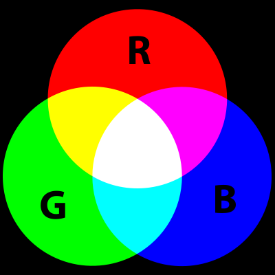
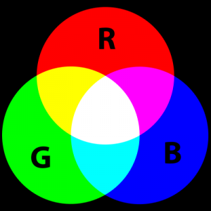
Figure 2 – Additive color primaries from Wikimedia Commons and in the public domain

There are two ways to create color: additive and subtractive.  Additive color starts with black and builds up from there with pure primaries, usually red, green, and blue.  Take a look at Figure 2.   You might imagine, for instance, that the image of Figure 2 was created with three slide projectors, projecting a red, a green, and a blue circle respectively.  Where they all mix equally you get white.  Essentially, any color can be achieved by varying the proportions of these three primary colors.

Subtractive Color System

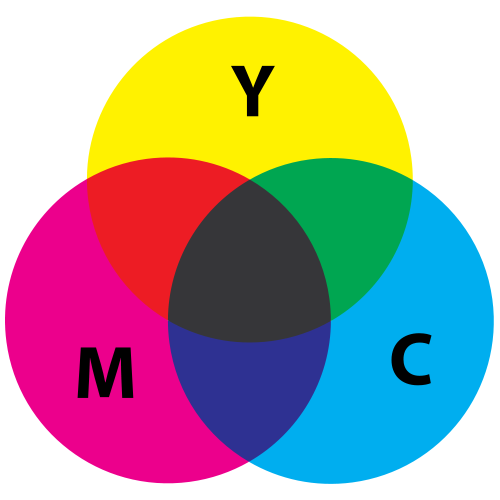
Figure 3 -Subtractive color primaries, from Wikicommons and in the public domain

Alternatively, see Figure 3, you can start with white and progressively subtract colors.  This is what happens when you mix paints.  Blue paint absorbs all colors except blue, which it reflects back at you.  Yellow paint reflects yellow light.  When the two colors are mixed you get green – as we all learned in kindergarten.  The usual primaries for subtractive color are yellow, magenta, and cyan.  You can think of the circles in Figure 3 as being filters of each of these three colors.  Where they all overlap, you get black, and every color in between black and white can be achieved by some mixture of the three.

DuHaurron1877

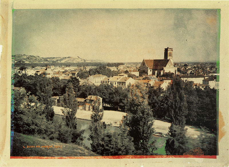
Figure 4 – Early subtractive color process by DuHaurron 1877, from Wikicommons and in the public domain

In future blogs I’m going to talk about various color processes.  Indeed, we have already spoken about the additive Autochrome process and looked at some examples.  So for fun, consider Figure 4 a photograph taken by Louis Arthur Ducos du Hauron (1837-1920) and created by the helichrome multilayer dichromated pigment process.  This is an early subtractive color process and if you examine the edges of the image you can quite clearly see the different pigment layers.


Photographic firsts #4 – the first aerial photograph

Nadar Aerial Photograph from Balloon Paris 1858

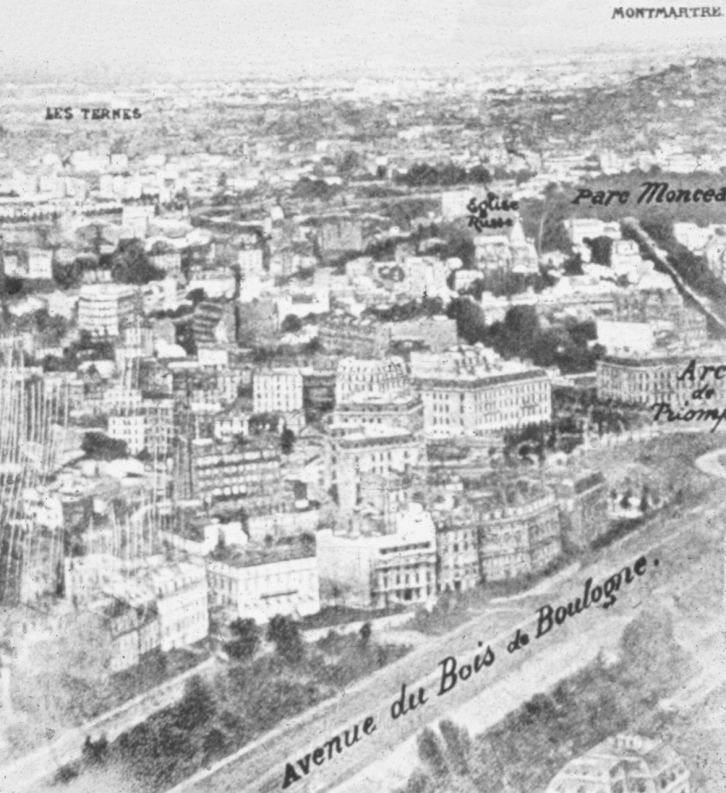
Figure 1 – Earliest remaining aerial photograph by Nadar. Over Paris in 1866 from the Wikicommons and in the public domain

I thought it would be fun today to consider another photographic first, in this case the world’s first aerial photograph.  The first known aerial photograph was taken from a tethered hot air balloon 80 m over the French village of Petit-Becetre in 1858 by French photographer and balloonist, Gaspar Felix Tournachon (aka Nadar).

balloon-Boston

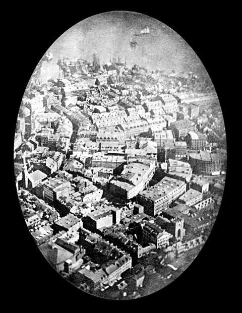
Figure 2 – Earliest known existent aerial photograph. Over Boston in 1858 by John Black from the Boston Public Library and in the public domain

Now the thing is that when we think about such an event, we tend to modernize it and imagine that we climb into a balloon with our digital SLR and snap snap snap.  However, we are talking 1858 and we are talking wet collodion photographic process.  Wet plates must be developed before the plate dries that is within 20 min of exposure.   As a result,  Nadar in addition to having to lug a large view camera into the balloon with him, had to build and use a whole darkroom on the balloon.  Pretty impressive! Unfortunately, the fruits of Nadar’s 1858 efforts no longer exist.  The earliest existent aerial phototograph from Nadar was taken over Paris in 1866 (see Figure 1).  As a result the earliest aerial photograph known to be still in existence is James Wallace Black’s image of Boston, also taken from a hot-air balloon but in 1860 (see Figure 2).  It is also interesting to see a side-by-side comparision with a modern shot with the same perspective taken by S. W. Dunwell on October 13 of 2012, that is to the minute 162 years apart.

Image stitching on the IPhone

Figure 1 - Panoramic Image of the Natick Mall taken with my IPhone 4s

Figure 1 – Panoramic Image of the Natick Mall taken with my IPhone 4s

I talked about image stitching in my blog of January 11 and there mentioned that it is possible, indeed pretty easy to do this with an IPhone or Adobe Photoshop.   A friend of mine’s eight year old daughter discovered it on his wife’s IPad and showed them how to do it.  Above is an example, a panoramic image of taken with my IPhone 4S.  I was going to give you instructions on how to do this, but discovered a little instruction video on the web.  Grid stitching is also available.  And you can also get $0.99 apps to make your life even easier.

Doing this in Adobe Photoshop is a bit counter intuitive.  Go to the “File” tab, chose “Automate” and finally “Photomerge.”  Again it makes a previously hard job really easy.  So then you get into the age old question.  Does making it easy lead to thousands of mediocre images?  Who cares.  Have a fun time being creative?

Early color photography – the autochrome process

AdditiveColor.svg

Figure 1 – The additive color wheel from the wikicommons b Mike Horvath New version by jacobolus and released to the public domain.

Yesterday we discussed the fact that color photography first became practical with the introduction of the Autochrome process in 1907.  Autochrome was patented by brothers Auguste Marie Louis Nicholas and Louis Jean Lumière  in 1903,  It was the dominant form of color photography until the introduction of Kodachrome in 1935.  As many photographers lament, Kodachrome succumbed to the commercial onslaught of digital photography and was withdrawn from the market in 2010.  Kodachrome had a very unique soft pastel quality.  I think that you will agree, after seeing some Autochrome images here, that Autochrome also had its own unique appearance and aesthetic quality.

Color Receptors Human Eye

Figure 2 – The spectral sensitivity of the S, L, and M type cones in the human eye. Image from the Wikicommons and in the public domain.

Autochrome was an additive process (see Figure 1).    The human eye has three types of color receptors, S, M, and L cone types, each with its own spectral sensitivity, as shown in Figure 2. .  Color vision, in its essence, comes from the relative excitation of the these three types of photoreceptor cells.In additive color a set of primary colors, usually red, green, and blue is used for illumination.   You might imagine, for instance, that the image of Figure 1 was created with three slide projectors, projecting a red, a green, and a blue circle respectively.  Where they all mix equally you get white.  Essentially, any color can be achieved by varying the proportions of these three primary colors.

Lumiere

Figure 3 – A closeup of the potato starch particles in an Autochrome from the Wkicommons and in the public domain

Your eye will respond accordingly.  What does that mean?  It means that the different cone types respond according to the responses shown in Figure 2.  These responses are then interpreted by the brain to perceive color.  This is what we mean by physiological optics.  It’s not just a question of the laws of optics.  It’s the laws of optics interpreted by the eye and the brain.  Some will recall Plato’s admonition against trusting the perception of our senses in seeking truth about the universe (see for instance, Richard Tarnas, “The Passion of the Western Mind“).

This kind of additive color process is exactly how a modern LED monitor works.  There are three light emitting diodes that make up a pixel.  Each with its own color spectrum.  We tend to take our technology for granted, which we really shouldn’t do.  Think about how minutely small these diodes need to be, how perfectly the thousands of them must be assembled to create a monitor, and finally recognize that there is so little room for error.  You wouldn’t accept a monitor with many bad pixels.  All of this is why new technologies are so expensive initially.

Taj_Mahal_1921

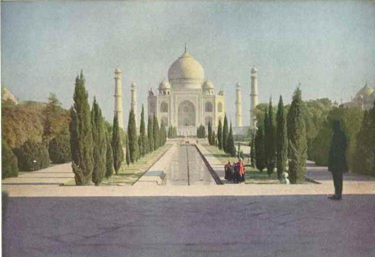
Figure 4 – The Taj Mahal an Autochrome taken by Helen Messinger Murdoch for the National Geographic Magazine, March 1921 from the Wikicommons and in the public domain.

The reason that I am blithering on about how marvelous our digital technology is, is that I now want you to image that it is over a hundred years ago.  The only tools that you have are analogue ones.  But you want to do the same thing.  You want to create a minute color pixel matrix.  How did the Lumiere brothers do it?  They used potato starch.  As a modern technology inventor, I stand in total and complete awe of them.

Nieuport_17_C.1

Figure 5 -n Autochrome of a Nieuport 23 C.1 fighter plane 1917 from the Wikicommons and in the public domain

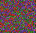
The Autochrome process works as follows.  An adhesive layer was coated onto a glass plate. Potato starch grains graded to 5 to 10 um where attached to this layer.  The starch grains were dyed with either red orange, green, or blue violet dye (an unusual color wheel). Gaps between the grains were filled with lamp black (essentially soot). A closeup of this “pixel” pattern is shown in Figure 3.   Note that if we are dealing with a two inch by two inch plate, this density corresponds to about a 5.3 MPz image – pretty impressive for 1907.  This fragile layer was coated with a shellac and then overlain with a conventional silver halide gelatin emulsion.  Because of the high sensitivity of these emulsion to UV light from the sun, a yellow orange filter needed to be placed in front of the camera lens when taking a photograph to block-out these rays.

Arnold_Genthe-California_golden_poppies,_Autochrome

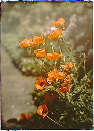
Figure 6 – California Golden Poppies an Autochrome taken between 1907 and 1911 by Arnold Genthe in the LOC from Wikicommons and in the public domain

When a photograph was taken the colored potato starch grains acted as minute filters.  The silver halide emulsion was developed by conventional means and then reversed to a positive by what is effectively a bleaching process.  Since the colored starch matrix remains intact, when the positive image (say illuminated from behind) will become colored as light passes back through the filter matrix.

This process very successfully creates color images, which certainly accounted for its popularity during the three decades of its dominance.  It should also be noted that towards the end of its commercial span roll film versions were also successfully introduced. Several examples of beautiful Autochromes are shown in Figures 4 to 6.